unity 3d drawing line in game
Lines, trails, and billboards
Line Renderer component
Switch to Scripting
The Line Renderer component takes an assortment of two or more points in 3D space, and draws a directly line between each one. You can utilize a Line Renderer to draw anything from a uncomplicated straight line to a circuitous screw.
The line is always continuous; if yous demand to depict two or more completely split up lines, you should use multiple GameObjects The key object in Unity scenes, which can represent characters, props, scenery, cameras, waypoints, and more than. A GameObject's functionality is defined by the Components attached to it. More info
See in Glossary , each with its own Line Renderer.
The Line Renderer does not return lines that accept a width in pixels The smallest unit in a calculator image. Pixel size depends on your screen resolution. Pixel lighting is calculated at every screen pixel. More than info
See in Glossary . It renders polygons that accept a width in world units. The Line Renderer uses the same algorithm for line rendering The procedure of drawing graphics to the screen (or to a render texture). Past default, the primary photographic camera in Unity renders its view to the screen. More than info
See in Glossary as the Trail RendererA visual effect that lets you to make trails behind GameObjects in the Scene as they motility. More info
Come across in Glossary .
Getting started
To create a Line Renderer:
- In the Unity bill of fare bar, get to GameObject > Effects > Line.
- Select the Line Renderer GameObject.
- Add together points to the Line Renderer's Positions array, either by direct setting array values in the Inspector A Unity window that displays information about the currently selected GameObject, asset or project settings, assuasive you lot to inspect and edit the values. More info
See in Glossary window or by using the Create Points Scene Editing Manner. - Use the Inspector window to configure the color, width, and other display settings of the line.
Line Renderer Materials
By default, a Line Renderer uses the built-in Material, Default-Line. You can make many changes to the appearance of the line without changing this Textile, such every bit editing the color slope or width of the line.
For other furnishings, such as applying a texture to the line, you will need to use a different Material. If you lot practise not want to write your ain Shader A programme that runs on the GPU. More info
See in Glossary for the new Fabric, Unity'due south built-in Standard Particle Shaders work well with Line Renderers.
See Creating and using Materials for more information.
Line Renderer Scene Editing Mode
You lot can use the Line Renderer'due south Inspector to change the Scene A Scene contains the environments and menus of your game. Think of each unique Scene file equally a unique level. In each Scene, y'all place your environments, obstacles, and decorations, essentially designing and building your game in pieces. More than info
See in Glossary Editing Mode. Different Scene Editing Modes enable you to apply the Scene view An interactive view into the world yous are creating. Yous employ the Scene View to select and position scenery, characters, cameras, lights, and all other types of Game Object. More than info
Meet in Glossary and the Inspector to edit the Line Renderer in different ways.
In that location are three Scene Editing Modes: None, Edit Points, and Create Points.
Setting the Scene Editing Mode

Use the Edit Points and Create Points buttons at the meridian of the Inspector to set the current Scene Editing Way.
Click the Edit Points push to set the Scene Editing Fashion to Edit Points. Click it again to ready the Scene Editing Mode to None.
Click the Create Points button to prepare the Scene Editing Way to Create Points. Click it over again to set the Scene Editing Mode to None.
Scene Editing Mode: None

When no Scene Editing Mode is selected, y'all tin can configure and perform a simplification operation that removes unnecessary points from the Positions array.
The following controls are visible in the Inspector:
| Control | Description |
|---|---|
| Simplify Preview | Enable Simplify Preview to come across a preview of the results of the simplification performance. |
| Tolerance | Set the amount by which the simplified line can deviate from the original line. A value of 0 results in no deviation, and therefore piffling or no simplification. Higher positive values result in more deviation from the original line, and therefore more simplification. The default value is 1. |
| Simplify | Click Simplify to reduce the number of elements in the Line Renderer's Positions array. The simplification operation uses the Ramer-Douglas-Peucker algorithm to reduce the number of points, based on the Tolerance value. |
Scene Editing Mode: Edit Points

When the Scene Editing Mode is set to Edit Points, Unity represents each signal in the Line Renderer'south Positions assortment as a xanthous sphere in the Scene view. You can move the individual points using the Move tool.
The following controls are visible in the Inspector:
| Control | Description |
|---|---|
| Show Wireframe | When enabled, Unity draws a wireframe in the Scene view that visualizes the line. |
| Subdivide Selected | This button is enabled when yous select two or more than adjacent points. Pressing this button inserts a new point between the selected adjacent points. |
Scene Editing Style: Create Points

When the Scene Editing Mode is prepare to Create Points, you tin can click inside the Scene view to add together new points to the end of the Line Renderer'south Positions array.
The post-obit controls are visible in the Inspector:
| Control | Description | |
|---|---|---|
| Input | Set the input method you want to use to create points. | |
| Mouse position | Create points based on the mouse position in the Scene view. | |
| Physics Raycast | Create points based on a raycast into the Scene. Unity creates the point at the position where the raycast hits. | |
| Layer Mask A value defining which layers to include or exclude from an operation, such as rendering, collision or your own lawmaking. More info Run into in Glossary | The layer mask to use when performing a raycast. This property is visible but when Input is set to Physics Raycast. | |
| Min Vertex Distance | When you drag the mouse to create points in the Scene view, the Line Renderer creates a new signal when this distance from the last point is exceeded. | |
| Offset | The showtime applied to created points. When Input is set to Mouse Position, Line Renderer applies the outset from the Scene camera A component which creates an prototype of a particular viewpoint in your scene. The output is either fatigued to the screen or captured every bit a texture. More info Run across in Glossary . When Input is fix to Physics Raycast, Line Renderer applies the offset from the raycast normal. | |
Line Renderer Inspector reference

This section contains the following sub-sections:
- Line settings
- MaterialsAn asset that defines how a surface should be rendered. More info
See in Glossary - Lighting
- Probes
- Additional Settings
Line settings
| Property | Function | |
|---|---|---|
| Loop | Enable this to connect the kickoff and concluding positions of the line, and class a closed loop. | |
| Positions | The array of Vector3 points to connect. | |
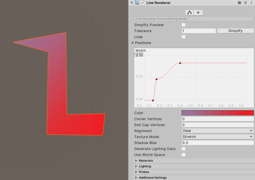
| Width | Define a width value, and a bend value to command the width of your line along its length. The bend is sampled at each vertex, so its accuracy is limited past the number of vertices in your line. The overall width of the line is controlled by the width value. | |
| Color | Define a gradient to command the color of the line along its length. Unity samples colors from the Color gradient at each vertex. Betwixt each vertex, Unity applies linear interpolation to colors. Adding more vertices to your line might give a closer approximation of a detailed gradient. | |
| Corner Vertices | This holding dictates how many actress vertices are used when cartoon corners in a line. Increment this value to make the line corners announced rounder. | |
| Stop Cap Vertices | This property dictates how many extra vertices are used to create cease caps on the line. Increase this value to make the line caps appear rounder. | |
| Alignment | Set the direction that the line faces. | |
| View | The line faces the Photographic camera. | |
| TransformZ | The line faces the Z axis of its Transform component A Transform component determines the Position, Rotation, and Scale of each object in the scene. Every GameObject has a Transform. More info Meet in Glossary . | |
| Texture Manner | Command how the Texture is practical to the line. | |
| Stretch | Map the texture once along the entire length of the line. | |
| Tile | Repeat the texture forth the line, based on its length in earth units. To set the tiling charge per unit, use Cloth.SetTextureScale. | |
| DistributePerSegment | Map the texture once along the entire length of the line, assuming all vertices are evenly spaced. | |
| RepeatPerSegment | Echo the texture forth the line, repeating at a rate of in one case per line segment. To adjust the tiling charge per unit, utilise Fabric.SetTextureScale. | |
| Shadow Bias | Set up the amount to move shadows away from the Light to remove shadowing artifacts cused past approximating a volume with billboarded geometry. | |
| Generate Lighting Data | If enabled, Unity builds the line geometry with normals and tangents included. This allows information technology to use Materials that use the Scene lighting. | |
| Use World Space | If enabled, the points are considered every bit world space coordinates. If disabled, they are local to the transform of the GameObject to which this component is attached. | |
Materials
The Materials section lists all the materials that this component uses.
| Property | Description |
|---|---|
| Size | The number of elements in the material list. If y'all decrease the number of elements, Unity deletes the elements at the end of the list. If you increase the number of elements, Unity adds new elements to the cease of the list. Unity populates new elements with the same textile that the chemical element at the end of the list uses. |
| Element | The materials in the list. You tin assign a material nugget to each element. By default, Unity orders the list alphabetically based on the name of the materials. This listing is reorderable, and Unity updates the number of the elements automatically as you lot alter their order. |
Lighting
The Lighting department contains properties that relate to lighting.
| Property | Clarification | |
|---|---|---|
| Cast Shadows | Specify if and how this Renderer casts shadows when a suitable Calorie-free shines on information technology. This property corresponds to the Renderer.shadowCastingMode API. | |
| On | This Renderer casts a shadow when a shadow-casting Lite shines on it. | |
| Off | This Renderer does not bandage shadows. | |
| Ii-sided | This Renderer casts ii-sided shadows. This ways that single-sided objects like a aeroplane or a quad tin can cast shadows, fifty-fifty if the light source is backside the mesh. For Broiled Global Illumination or Enlighten Realtime Global Illumination to support two-sided shadows, the material must support Double Sided Global Illumination. | |
| Shadows Only | This Renderer casts shadows, but the Renderer itself isn't visible. | |
| Receive Shadows | Specify if Unity displays shadows cast onto this Renderer. This property merely has an event if y'all enable Broiled Global Illumination or Enlighten Realtime Global Illumination for this scene. This property corresponds to the Renderer.receiveShadows API. | |
| Contribute Global Illumination | Include this Renderer in global illumination calculations, which accept place at bake time. This property only has an result if you enable Broiled Global Illumination or Enlighten Realtime Global Illumination for this scene. Enabling this property enables the Contribute GI flag in the GameObject'due south Static Editor Flags. It corresponds to the StaticEditorFlags.ContributeGI API. | |
| Receive Global Illumination | Whether Unity provides global illumination data to this Renderer from broiled lightmaps, or from runtime Light Probes. This belongings is simply editable if you enable Contribute Global Illumination. It only has an effect if you enable Baked Global Illumination or Enlighten Realtime Global Illumination for this scene. This property corresponds to the MeshRenderer.receiveGI API. | |
| Lightmaps | Unity provides global illumination information to this Renderer from lightmaps. | |
| Light Probes | Unity provides global illumination information to this Renderer from Light ProbesCalorie-free probes store information most how low-cal passes through space in your scene. A drove of calorie-free probes arranged within a given space can improve lighting on moving objects and static LOD scenery inside that space. More info See in Glossary in the scene. | |
| Prioritize Illumination | Enable this belongings to always include this Renderer in Enlighten Realtime Global Illumination calculations. This ensures that the Renderer is affected by distant emissives, fifty-fifty those which are usually excluded from Global Illumination calculations for operation reasons. This property is visible simply if Contribute GI is enabled in the GameObject's Static Editor Flags, your project uses the Built-in Render Pipeline, and Enlighten Realtime Global Illumination is enabled in your scene. | |
Probes
The Probes department contains backdrop relating to Light Probe and Reflection ProbesA rendering component that captures a spherical view of its surroundings in all directions, rather similar a camera. The captured image is and so stored as a Cubemap that can be used by objects with reflective materials. More info
See in Glossary .
| Property | Description | |
|---|---|---|
| Light Probes | Fix how this Renderer receives light from the Light Probes system. This property corresponds to the Renderer.lightProbeUsage API. | |
| Off | The Renderer doesn't employ whatever interpolated Light Probes. | |
| Blend Probes | The Renderer uses one interpolated Light Probe. This is the default value. | |
| Use Proxy Volume | The Renderer uses a 3D grid of interpolated Light Probes. | |
| Custom Provided | The Renderer extracts Calorie-free Probe shader uniform values from the MaterialPropertyBlock. | |
| Proxy Volume Override | Set a reference to another GameObject that has a Low-cal Probe Proxy Book component. This holding is only visible when Light Probes is set up to Use Proxy Volume. | |
| Reflection Probes | Prepare how the Renderer receives reflections from the Reflection Probe system. This property corresponds to the Renderer.probeAnchor API. | |
| Off | Disables Reflection Probes. Unity uses a skybox for reflection. | |
| Blend Probes | Enables Reflection Probes. Blending occurs only between Reflection Probes. This is useful in indoor environments where the character may transition between areas with different lighting settings. | |
| Alloy Probes and Skybox | Enables Reflection Probes. Blending occurs betwixt Reflection Probes, or between Reflection Probes and the default reflection. This is useful for outdoor environments. | |
| Simple | Enables Reflection Probes, but no blending occurs betwixt Reflection Probes when there are ii overlapping volumes. | |
| Anchor Override | Prepare the Transform that Unity uses to determine the interpolation position when using the Calorie-free Probe or Reflection Probe systems. By default, this is the centre of the bounding box of the Renderer'south geometry. This property corresponds to the Renderer.probeAnchor API. | |
Additional Settings
The Additional Settings department contains boosted backdrop.
| Property | Description | |
|---|---|---|
| Motion Vectors | Set whether to utilise motion vectors to runway this Renderer's per-pixel, screen-space motion from ane frame to the next. You tin use this information to employ post-processing effects such as movement mistiness. Note: not all platforms back up motion vectors. See SystemInfo.supportsMotionVectors for more information. This property corresponds to the Renderer.motionVectorGenerationMode API. | |
| Photographic camera Movement Only | Use only Camera movement to track motion. | |
| Per Object Motion | Use a specific pass to runway movement for this Renderer. | |
| Force No Motion | Do not track motility. | |
| Dynamic Occlusion | When Dynamic Occlusion is enabled, Unity's occlusion alternativeA feature that disables rendering of objects when they are not currently seen by the camera because they are obscured (occluded) past other objects. More than info See in Glossary arrangement culls this Renderer when it is blocked from a Camera's view past a Static Occluder. Otherwise, the organisation does not cull this Renderer when it is blocked from a Photographic camera's view by a Static Occluder. Dynamic Apoplexy is enabled by default. Disable information technology for effects such as drawing the outline of a character behind a wall. | |
| Sorting Layer | The name of this Renderer's Sorting Layer. | |
| Order in Layer | This Renderer's lodge within a Sorting Layer. | |
Lines, trails, and billboards
Source: https://docs.unity3d.com/Manual/class-LineRenderer.html
0 Response to "unity 3d drawing line in game"
Post a Comment